
Core Summary: Color difference in PECVD coating traces to graphite boat thermal field non-uniformity. Non-equidistant plate spacing and proper saturation reduce scrap.
What Causes Color Difference in PECVD Coating?
Key takeaway: Color difference is a film thickness problem, and the graphite boat‘s thermal field distribution is often the root cause. Fixing the boat‘s thermal behavior is the most effective way to reduce color difference scrap.
Color difference — the variation in visual appearance across wafers after silicon nitride deposition — is one of the most persistent quality problems on a solar cell PECVD line. It‘s also one of the most misunderstood.
The root cause is almost always thickness variation in the silicon nitride film. When the film is slightly thicker or thinner at different points on a wafer, the optical path length changes, and the wafer reflects light differently. That‘s the color difference you see.
The question is what causes the thickness variation. Process gases? RF power? Temperature? All of these can contribute. But in many production lines, the graphite boat is a major factor — specifically, how the boat distributes heat and plasma across the wafer positions.
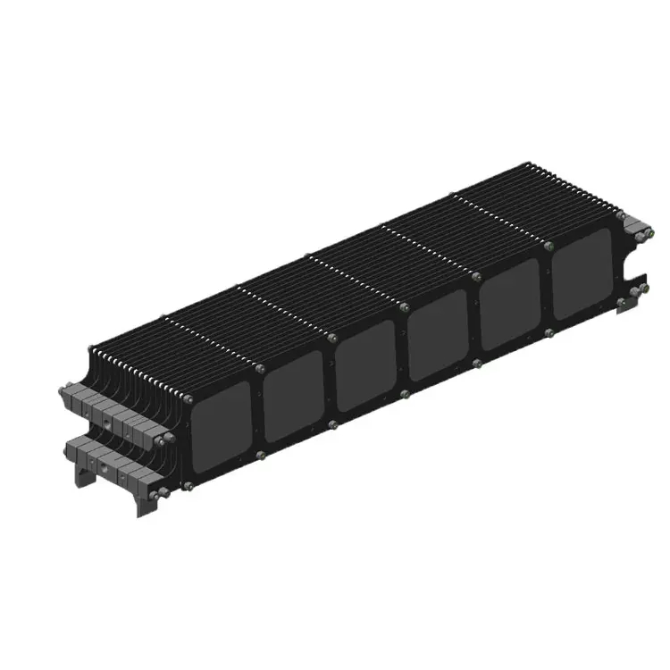
In a tubular PECVD system, the graphite boat sits inside the furnace tube and holds hundreds of wafers at precise intervals. The plasma is generated between adjacent boat plates. The wafer at each position sees a slightly different plasma environment depending on its position in the boat. Wafers at the center see a different environment than wafers at the edges.
Patent CN224212761U describes the problem directly: the temperature inhomogeneity of the graphite boat leads to uneven deposition rate and thickness of the silicon nitride film, resulting in uneven film thickness and color differences.
The Science Behind Thermal Field Non-Uniformity
Key takeaway: Color difference comes from two sources: non-uniform plasma potential between outer and center wafers, and non-uniform temperature distribution across the boat. Both are design and operational issues, not process recipe issues.
To understand why the boat causes color difference, you need to look at what‘s happening inside the furnace at the plasma level.
The PECVD process uses RF power to generate a plasma between the boat plates. The silicon wafers sit in slots on the boat, and the plasma deposits silicon nitride on their surfaces. The deposition rate depends on plasma density, which depends on the electric field between adjacent plates.
In a standard equidistant boat — where the spacing between every plate is the same — the wafers at the outer positions of the boat experience a different electric field than the wafers at the center. The outer wafers have fewer adjacent plates, so the potential difference between the outer layers is higher. That higher potential difference changes the plasma density and, therefore, the deposition rate.
The result: outer wafers get thicker or thinner films than center wafers. That shows up as color difference.
There‘s also a temperature component. The graphite boat heats up during the PECVD process, and the temperature distribution across the boat is not perfectly uniform. Areas with higher temperature have higher deposition rates. Areas with lower temperature have lower deposition rates. The temperature non-uniformity — typically ±5°C or more across a production boat — translates directly into film thickness variation.
How Non-Equidistant Designs Solve the Problem
Key takeaway: Non-equidistant plate spacing is the most effective design change for reducing color difference. It‘s a boat design issue, not a process recipe issue.
The most effective design change for reducing color difference is switching from an equidistant boat to a non-equidistant design.
Patent CN224212761U describes the concept: the spacing between adjacent boat plates gradually increases from the center to the edges. This reduces the potential difference when adjacent outer layers discharge, optimizing the color difference caused by temperature variation and achieving consistent film appearance.
The physics is straightforward. By increasing the spacing at the outer positions, you reduce the electric field strength between the outer plates. That reduces the plasma density difference between center and outer positions, which balances the deposition rate across the entire boat.
Table 1: Equidistant vs Non-Equidistant Boat Design
| Parameter | Standard Equidistant | Non-Equidistant Design |
|---|---|---|
| Plate spacing | Uniform throughout | Increases from center to edges |
| Outer wafer plasma | Higher potential difference | Reduced potential difference |
| Film thickness uniformity | ±3–5% across boat | ±2–3% across boat |
| Color difference scrap rate | Baseline | Reduced |
| First-pass yield | Baseline | Higher |
| Rework and breakage | Baseline | Lower |
Source: Patent CN224212761U and production data from Chinese cell manufacturers.
The patent also notes that the non-equidistant design reduces rework and breakage rates, increases first-pass yield, and lowers costs. For a 2 GW line, even a 1% improvement in first-pass yield translates to millions of wafers per year.
The Saturation Window: Why New Boats Underperform
Key takeaway: New boats need about 30 runs to reach optimal uniformity. Saturation pre-treatment is not optional — it‘s the difference between a smooth ramp-up and weeks of color difference scrap.
Here‘s something that surprises many engineers: a brand-new graphite boat doesn‘t perform at its best right out of the box. In fact, the first 30 runs are usually the worst.
When a new boat enters the PECVD chamber, the graphite surface is unsaturated. Residual plasma deposits form unevenly during the first few runs, and the deposition rate varies across the boat. As the boat accumulates deposition cycles, the surface layer gradually stabilizes, and inter-wafer uniformity improves.
The saturation process — a controlled pre-treatment that deposits a thin silicon nitride layer on all graphite surfaces before production — accelerates this stabilization. Without it, the first 30 production runs will have higher color difference scrap rates.
After about 30 runs, the boat reaches optimal condition. From that point, uniformity is stable — until film buildup at the contact edges starts to change the electric field. The edge regions get stronger, more plasma deposits there, and edge whitening appears. That‘s the signal that the boat needs cleaning.
Table 2: Color Difference Risk Over Boat Lifespan
| Usage Stage | Boat Condition | Color Difference Risk |
|---|---|---|
| 0–10 runs (no saturation) | Unsaturated, unstable | High |
| 0–30 runs (with saturation) | Gradually stabilizing | Decreasing |
| 30 runs | Fully saturated | Lowest |
| 30–100 runs | Slow film buildup | Low, gradually increasing |
| 100+ runs | Significant buildup | High (edge whitening) |
Source: Production data from PECVD coating operations.
A Real Case: Cutting Color Difference Scrap by 39%
Key takeaway: Color difference is often a boat design or condition issue, not a process recipe issue. Fixing the boat can recover significant yield without touching the process parameters.
A 2 GW TOPCon cell line in eastern China was running three tubular PECVD systems with standard equidistant graphite boats. Color difference scrap was running at about 1.8% of total production — roughly 1,800 wafers per day on that line.
The engineering team checked the usual suspects first: gas flow rates, RF power stability, process temperature. Everything was within spec. The color difference wasn‘t uniform — it clustered on the outer wafer positions of each boat. That was the first clue that the boat design was involved.
They switched to a non-equidistant boat design, with plate spacing increasing by about 15% from center to edges. After a two-week saturation period, the color difference scrap rate dropped to 1.1%. That‘s a 39% reduction in appearance-related scrap, recovered without any process recipe changes.
The team also tightened their cleaning schedule from 120 runs to 80 runs. This added cleaning cost but reduced edge whitening and prevented permanent surface damage, extending the boat‘s useful life.
Frequently Asked Questions
Q1: Why does color difference cluster on outer wafer positions?
Because outer wafers experience a different plasma environment than center wafers. In an equidistant boat, the potential difference between outer plates is higher, which changes the plasma density and deposition rate. Non-equidistant boat designs address this by increasing spacing at the outer positions.
Q2: How long does it take for a new boat to reach optimal uniformity?
About 30 runs with proper saturation pre-treatment. Without saturation, the stabilization period is longer and the scrap rate during that period is higher. The saturation process deposits a thin nitride layer on the graphite surfaces before production, accelerating the stabilization.
Q3: Can I fix color difference by adjusting the process recipe?
Sometimes, but it‘s often the wrong approach. If the color difference clusters on outer wafer positions and the boat is an equidistant design, the root cause is the boat, not the process. Adjusting the recipe to compensate for a boat design issue usually creates other problems elsewhere.
Q4: What‘s edge whitening, and what does it mean?
Edge whitening is a visual defect that appears on coated wafers when film buildup on the boat‘s contact edges changes the electric field. The edge regions get stronger plasma, more deposition happens there, and the wafer edges appear whiter than the center. It‘s a signal that the boat needs cleaning.
Q5: How much does a non-equidistant boat design cost compared to a standard boat?
The manufacturing cost difference is small — it‘s a design change in the plate spacing, not a material change. The main cost is the engineering time to design and validate the new spacing profile for your specific furnace and process. For most lines, the yield recovery pays back the engineering cost within a few months.
Summary and How VET Energy Can Help
Color difference is one of the most frustrating yield losses on a PECVD line because it‘s often treated as a process problem when it‘s actually a boat problem. The graphite boat‘s thermal field distribution and plasma behavior determine whether wafers come out with uniform film thickness or visible color variation.
At VET Energy, we work with cell manufacturers to design graphite boats that minimize color difference — from non-equidistant plate spacing to optimized pin geometry to surface treatments that stabilize plasma behavior. Dr. Wang, our technical lead, has 12 years of experience in graphite component design and PECVD process support.
If you‘re dealing with persistent color difference scrap that process adjustments haven‘t fixed, contact us for a technical review. We‘ll look at your boat design and process parameters and recommend a path forward.
References
- Patent CN224212761U — Novel graphite boat. Hubei Huachang Energy Technology Co., Ltd., 2026. (Non-equidistant plate spacing design for color difference reduction)
- CN103614708A — Graphite boat with gradient type spacing. 2013. (Gradient spacing design for antireflective coating uniformity)
- CN109183000A — Graphite boat saturation process. 2019. (Saturation process for reducing color differencer
Post time: Mar-22-2024