
Core Summary: Graphite boats carry wafers through high-temperature PECVD processes. This guide covers working principles, material grades, key specs, and how to select the right boat for your line.
What Is a Graphite Boat?
Key takeaway: Graphite boats are not passive carriers — their geometry and material quality directly influence film uniformity, wafer yield, and overall production cost.
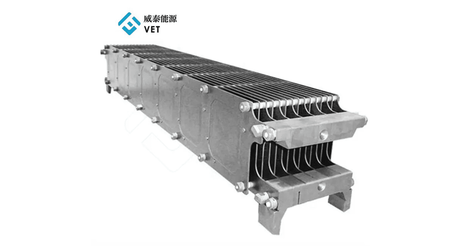
A graphite boat is a precision-machined carrier that holds silicon wafers during high-temperature processes like PECVD, diffusion, and annealing. It sits inside a furnace tube, supports dozens to hundreds of wafers at precise spacing, and must survive repeated thermal cycling above 2000°C without deforming or contaminating the wafers it carries.
The key word here is “precision.” A graphite boat isn‘t just a rack. The slot geometry, pin depth, and surface finish directly affect whether your wafers get uniform coating or come out with color variations. We’ll get into that below.
How a Graphite Boat Works in PECVD
Key takeaway: Uniform gas flow, consistent resistivity, and stable slot geometry are the three pillars of good PECVD performance. Any one of them being off will show up as coating defects.
Inside a tubular PECVD system, the graphite boat serves three functions simultaneously: mechanical support, electrical conduction, and thermal distribution.
The boat must hold each wafer at a consistent gap so process gases (silane, ammonia, etc.) flow uniformly through every interspace. The gaps need to be wide enough for gas to pass, but tight enough to maintain plasma density between wafers. If the spacing is off, some wafers get thick films while others get thin ones — that‘s how you end up with color difference scrap.
The graphite material itself must have consistent resistivity so the boat conducts RF power evenly. Resistivity typically ranges from 8–13 μΩm for PECVD-grade graphite. When resistivity varies across the boat, plasma intensity varies too, and so does film thickness.
Types of Graphite Boats: PV-Grade vs Semiconductor-Grade
Key takeaway: PV-grade graphite boats prioritize cost and throughput. Semiconductor-grade boats prioritize purity and thermal stability. Choosing the wrong grade for your application is the most common and most expensive mistake.
Not all graphite boats are built the same. The two major categories — photovoltaic and semiconductor — have different purity, density, and mechanical requirements.
Comparison Table: PV-Grade vs Semiconductor-Grade Graphite Boats
| Parameter | PV-Grade | Semiconductor-Grade |
| Bulk density | ≥1.78 g/cm³ | ≥1.85 g/cm³ |
| Open porosity | ≤12% | ≤8% |
| Flexural strength | ≥40 MPa | ≥60 MPa |
| Ash content | ≤0.1% (1000 ppm) | ≤50 ppm (often ≤5 ppm) |
| Thermal expansion (20–1000°C) | ~4.5×10⁻⁶/°C | ~3.8×10⁻⁶/°C |
| Thermal conductivity (25°C) | 95–110 W/m·K | 115–135 W/m·K |
Data compiled from industry white papers and graphite material datasheets.
The biggest gap isn‘t density — it’s purity. PV-grade boats can tolerate around 0.1% ash content. For semiconductor applications, that number needs to drop to 50 ppm or lower, and critical elements like boron and phosphorus must be controlled at the ppb level. Even 100 ppb of boron in a graphite boat can diffuse into molten germanium during crystal growth and flip its electrical type — that‘s a whole batch of expensive material down the drain.
Key Parameters When Selecting a Graphite Boat
Key takeaway: Don’t just buy on density and price. Resistivity uniformity, CTE match, slot geometry, and surface coating all determine how the boat performs on your line.
Beyond density and purity, engineers should pay attention to a few parameters that often get overlooked during procurement but show up as problems on the production floor.
Resistivity uniformity. The boat‘s electrical resistance must be consistent across its entire surface. Resistivity typically sits between 8–13 μΩm for PECVD use. Hot spots mean uneven plasma, which means uneven coating.
Thermal expansion match. The graphite‘s coefficient of thermal expansion (CTE) needs to be close to that of silicon. If the mismatch is too large, the boat can deform during thermal cycling, causing wafer misalignment or, worse, cracked wafers. PV-grade CTE is around 4.5×10⁻⁶/°C, while semiconductor-grade can go as low as 3.8×10⁻⁶/°C.
Slot geometry. Pin slot depth is typically 0.5–1 mm, with 0.6–0.8 mm being the sweet spot for most tubular PECVD systems. The slot pitch (spacing between adjacent wafer positions) must match your process recipe’s wafer-to-wafer gap. These aren‘t universal specs — they should be matched to your specific equipment, not picked from a catalog.
Surface treatment. Uncoated graphite is porous and will adsorb moisture and oxygen. A SiC or TaC coating can seal the surface, improve chemical resistance, and extend boat life. TaC coatings, for example, remain stable above 2200°C and have been shown to reduce micropipe defects in SiC crystal growth by up to 99.7%.
A Real Case: When a Five-Pin Design Fails
Key takeaway: A boat design that “looks right” on paper can fail in production due to kinematic indeterminacy. Always validate pin geometry with actual loading tests.
Here‘s a case that illustrates why design details matter more than material specs alone.
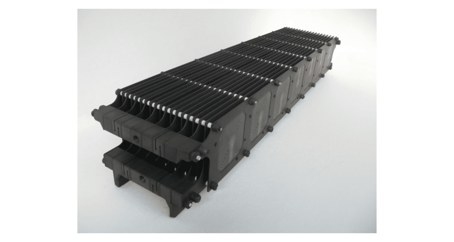
A PECVD production line was using a five-pin graphite boat to hold silicon wafers during coating. On paper, five contact points should provide better support than three. In practice, the opposite happened. Production data showed that the wafer didn’t seat deterministically on all five pins. The active contact condition shifted with every robotic placement, machining variation, and thermal load. Over 100 loading cycles, the wafers kept misaligning. The result: process aborts in over 45% of production test runs.
The team redesigned the boat with a three-pin gravity-wedge configuration based on kinematic design principles. Reaction-force analysis confirmed positive support at both room temperature and 500°C. The asymmetric three-pin layout used gravity to wedge the wafer into a repeatable position. Wafer misalignment dropped sharply, and the process became stable.
The lesson: more contact points don‘t automatically mean better stability. Deterministic constraint — where the wafer has exactly one way to sit — matters more than the number of pins.
Summary and How VET Energy Can Help
Choosing the right graphite boat isn‘t just about picking a material grade from a datasheet. It’s about matching the boat‘s thermal behavior, electrical properties, and slot geometry to your specific PECVD process. Get that match right, and you get uniform films, stable yield, and predictable maintenance cycles. Get it wrong, and you’ll spend months chasing color difference scrap and unexplained process aborts.
At VET Energy, our engineering team works directly with customers to define the right boat specification — from material grade selection to slot geometry to surface coating. Dr. Wang, our technical lead, has over 12years of experience in graphite component design for semiconductor and photovoltaic applications.
If you‘re evaluating graphite boats for a new line or troubleshooting existing performance issues, contact us for a technical consultation. We’ll review your process requirements and recommend a specification that fits.
References
Graphite Boat Quality Selection Technical White Paper — XRD Graphite Manufacturing, 2025. (PV-grade and semiconductor-grade parameter comparison)
US Patent 10,151,030 B2 — Protective Layer for PECVD Graphite Boats, KGT Graphit Technologie GmbH, 2018. (Gas flow uniformity and plasma formation requirements)
Kaushik, S. “Kinematic and Static Equilibrium Analysis of Five-Pin and Three-Pin Graphite Boat Designs for Stable PECVD Wafer Handling.” IEEE PVSC. (Case study: five-pin vs three-pin design failure analysis)
Momentive Technologies. Tantalum Carbide (TaC) Coatings for SiC/GaN Epitaxial Reactor Components. (TaC coating performance data)
SEMI C-001 — Specification for High-Purity Graphite. SEMI International Standards. (Semiconductor-grade metallic contamination limits)
Graphite Matrix LLC. Graphite Boats — Technical Overview. (Thermal properties and high-temperature resistance)
Post time: Apr-22-2025