
Core Summary: How to select photovoltaic graphite boats for PERC, TOPCon, and HJT lines. Covers thermal uniformity, coating options, and maintenance tips from VET Energy engineers.
Why the Graphite Boat Is the Most Underrated Component in Solar Cell Manufacturing
Key takeaway: The graphite boat directly affects film uniformity, wafer breakage rate, and PECVD coating quality. Choosing one based on price alone usually costs more in the long run.
If you work on a solar cell production line, you already know the graphite boat gets blamed for a lot — color difference, film thickness variation, broken wafers. But is it always the boat‘s fault? Not necessarily. Still, the boat is almost always involved.
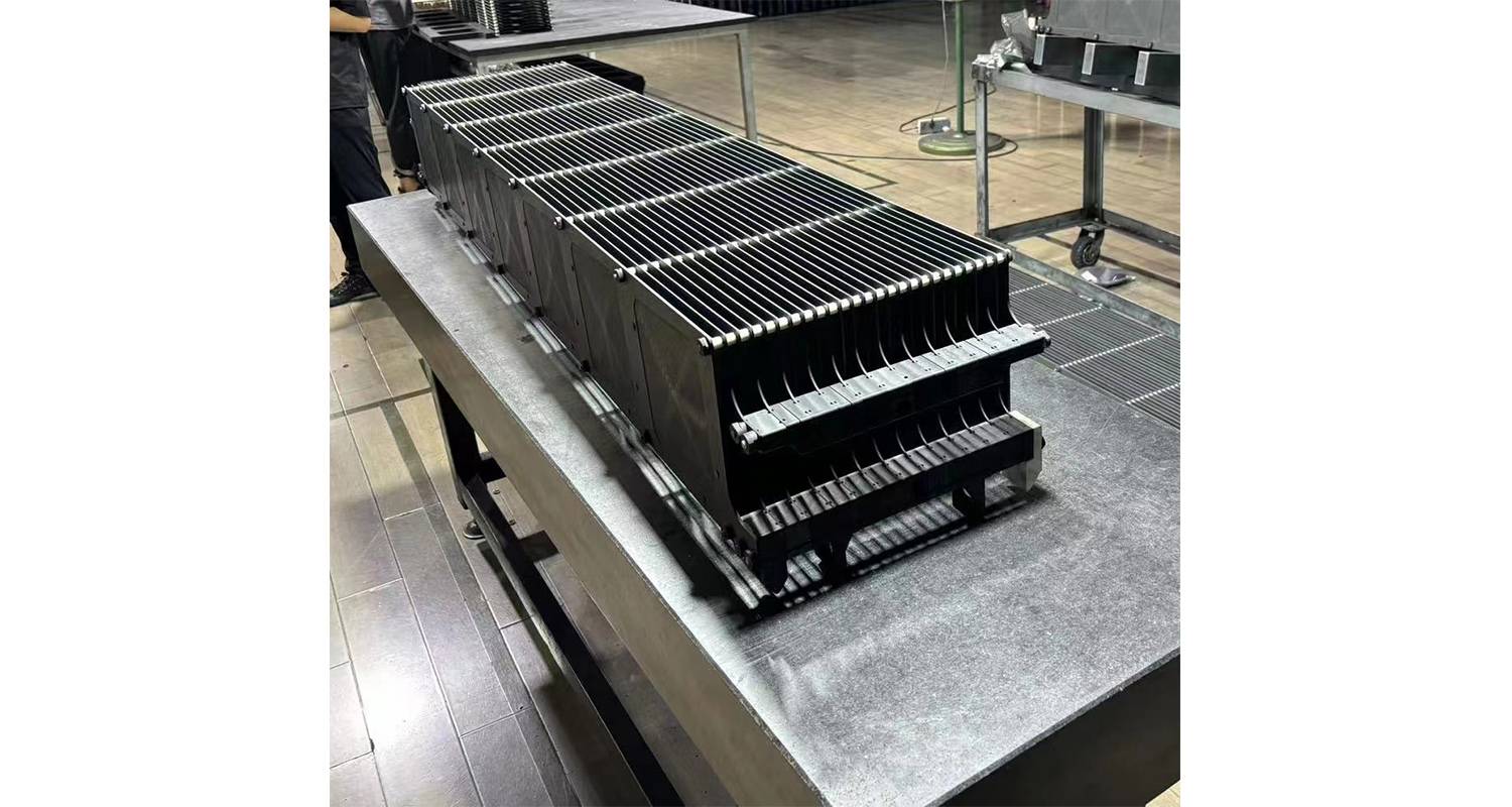
Here’s the reality: a solar cell PECVD boat can hold 200 to 400 silicon wafers per run, and each wafer is worth real money by the time it reaches the coating stage. A boat that loads unevenly, heats unevenly, or conducts unevenly will turn a high-yield run into a batch of scrap. That‘s why the top cell makers treat boat selection as a strategic decision, not a purchasing formality.
In this guide, we’ll cover what actually matters when selecting a photovoltaic graphite boat: the material specs, the design details, the coating choices, and how all of these connect to your line’s yield and cost per wafer.
Understanding the Graphite Boat‘s Role in PECVD
Key takeaway: The boat must simultaneously carry wafers, conduct RF power, and distribute heat evenly. A weak link in any of these three functions shows up as film defects and yield loss.
In tubular PECVD systems — the workhorse of silicon nitride anti-reflective coating — the graphite boat does three jobs at once.
First, it carries the wafers. Silicon wafers sit in slots (called “pin slots” or “卡点” in Chinese) machined into graphite plates. Slot depth is typically 0.5–1 mm, with 0.6–0.8 mm being the standard for most tubular systems.
Second, it conducts RF power. The boat acts as an electrode, distributing plasma between wafers. If the boat‘s resistivity varies, plasma density varies, and film thickness follows.
Third, it manages heat. The boat is exposed to temperatures of 400–600°C in the PECVD process, and it needs to distribute that heat evenly across every wafer position.
If any one of these functions is compromised, the result shows up on the production line. The most common symptom is color difference — wafers with visible color variations caused by non-uniform silicon nitride film thickness. Temperature non-uniformity of the graphite boat leads to uneven deposition rates, which directly causes thickness and color differences across the wafer batch.
PV-Grade Graphite Boat Specifications: What to Look For
Key takeaway: Focus on density, ash content, resistivity, and thermal expansion. These four parameters determine how the boat performs across its entire lifespan, not just on day one.
When evaluating a photovoltaic graphite boat, start with the material specs. They set the ceiling for how well the boat can perform.
Table 1: Key Specifications for PV-Grade PECVD Graphite Boats
| Parameter | Typical Value | Why It Matters |
|---|---|---|
| Bulk density | ≥1.80 g/cm³ | Higher density = slower oxidation, longer life |
| Ash content | ≤0.1% (1000 ppm) | Lower ash = fewer metal contaminants |
| Resistivity | 8–13 μΩ·m | Consistent resistivity = uniform plasma |
| Flexural strength | ≥40 MPa | Prevents breakage during thermal cycling |
| Thermal expansion (20–1000°C) | ~4.5×10⁻⁶/°C | Must match silicon to avoid warping |
| Thermal conductivity | 95–130 W/m·K | Higher conductivity = better heat distribution |
| Shore hardness | ≥55 HSD | Surface wear resistance |
Data compiled from industry specifications and supplier datasheets
What many people miss: The ash content specification is where PV-grade and semiconductor-grade diverge sharply. PV-grade boats can tolerate around 0.1% ash. Semiconductor-grade requires ≤50 ppm — a 20× difference. For solar cell production, PV-grade is sufficient and more cost-effective. But if you‘re processing high-efficiency cells or experimenting with new architectures, tighter purity control starts to matter more.
Thermal Uniformity: The Real Cause of Color Difference Scrap
Key takeaway: New boats need a saturation period (about 30 runs) to reach optimal uniformity. Plan for this in your production schedule, and monitor edge whitening as a signal that the boat needs cleaning or replacement.
Color difference is the most common quality complaint on a PECVD line, and the graphite boat is almost always part of the story. But the root cause is more specific than most people realize.
In a standard equidistant graphite boat, the spacing between adjacent boat plates is the same from the center to the edges. This seems logical — uniform spacing should give uniform plasma. But it doesn‘t work that way in practice.
The wafers at the outer positions of the boat are surrounded by fewer adjacent wafers. During plasma discharge, the potential difference between outer layers is higher, which changes the deposition rate. The result: outer wafers get thicker or thinner films than center wafers, and that shows up as color difference.
How Non-Equidistant Designs Solve the Problem
A recent patent (CN224212761U) describes a straightforward fix: non-equidistant fixed-interval design. The spacing between adjacent boat plates gradually increases from the center to the edges. This reduces the potential difference between adjacent outer layers during discharge, balancing the deposition rate across all wafer positions. The result is consistent film appearance and reduced color difference.
Table 2: Equidistant vs Non-Equidistant Boat Design
| Parameter | Standard Equidistant | Non-Equidistant Design |
|---|---|---|
| Plate spacing | Uniform throughout | Increases from center to edges |
| Outer wafer plasma | Higher potential difference | Reduced potential difference |
| Film thickness uniformity | ±3–5% across boat | ±2–3% across boat |
| Color difference scrap rate | Baseline | Reduced |
| Yield impact | Baseline | Higher first-pass yield |
Source: Patent CN224212761U and production data from Chinese cell manufacturers
Boat Condition Affects Uniformity: The 30-Run Saturation Window
Key takeaway: New boats need a saturation period (about 30 runs) to reach optimal uniformity. Plan for this in your production schedule, and monitor edge whitening as a signal that the boat needs cleaning or replacement.
Here‘s something we‘ve learned from working with cell manufacturers: a brand-new graphite boat doesn‘t perform at its best right out of the box.
When a new boat is first used, residual plasma deposits form unevenly on the graphite surfaces. During the first 30 runs or so, this deposit layer gradually stabilizes, and inter-wafer uniformity actually improves. After about 30 runs, the boat reaches its optimal condition. But beyond that point, film buildup at the contact edges starts to change the electric field. The edge regions get stronger, more plasma deposits there, and you start seeing edge whitening — a classic sign that the boat needs attention.
Table 3: Uniformity Changes Over Boat Lifespan
| Usage Stage | Boat Condition | Inter-Wafer Uniformity |
|---|---|---|
| 0–30 runs | New, unsaturated | Improving but not optimal |
| 30 runs | Fully saturated | Optimal |
| 30–100 runs | Gradual film buildup | Slowly degrading |
| 100+ runs | Significant buildup | Edge whitening appears |
Source: Production data analysis from PECVD coating operations
This saturation window is why proper pre-treatment (saturation) of new boats is standard practice in well-run fabs. Skipping it means running production with a boat that hasn‘t stabilized yet — and that means unnecessary color difference scrap in the first weeks.
A Real Case: How One Line Cut Color Difference Scrap
Key takeaway: Color difference is often a boat design or condition issue, not a process recipe issue. Fixing the boat can recover yield without touching the process.
A 2 GW TOPCon cell line in eastern China was struggling with color difference. The line ran three tubular PECVD systems with standard equidistant graphite boats. Scrap rates from color difference were running at about 1.8% of total production. For a line at that scale, that‘s roughly 1,800 wafers per day being scrapped for appearance defects alone.
The engineering team started by checking the usual suspects: gas flow rates, RF power stability, process temperature. Everything was within spec. The color difference wasn‘t uniform — it clustered on the outer wafer positions of each boat.
They switched to a non-equidistant boat design, with plate spacing increasing by about 15% from center to edges. After a two-week saturation period, the color difference scrap rate dropped to 1.1%. That‘s a 39% reduction in appearance-related scrap, recovered without any process recipe changes.
The team also tightened their boat maintenance schedule, cleaning boats at 80 runs instead of the previous 120 runs. This added cleaning cost but reduced edge whitening and extended the boat‘s useful life by preventing permanent surface damage.
3SiH4+4NH3 → Si3N4+12H2
Coating Options: SiC and TaC for Longer Boat Life
Key takeaway: SiC coating is the sweet spot for most PV lines — good protection, reasonable cost, proven in high-volume production. TaC is reserved for processes where SiC isn‘t sufficient.
Uncoated graphite is porous. In a PECVD environment, that porosity adsorbs moisture and process gases, which leads to particle generation and slow surface degradation. A protective coating seals the surface and extends boat life.
Two coatings dominate the market:
CVD SiC coating. Silicon carbide provides excellent thermal stability up to about 1,200°C and good corrosion resistance against the fluorine-based chemistries used in PECVD cleaning. It‘s the standard choice for most PV applications.
CVD TaC coating. Tantalum carbide offers higher temperature stability (stable above 2,200°C) and better resistance to aggressive atmospheres. It‘s more expensive and typically reserved for semiconductor applications or the most demanding PV processes.
The practical difference for a PV line: SiC coating extends boat life by reducing oxidation and surface erosion. Users report that coated boats maintain surface roughness (Ra) around 0.2–0.4 μm, compared to uncoated boats that degrade more quickly.
Table 4: Coating Comparison for PV Graphite Boats
| Property | Uncoated Graphite | CVD SiC Coated | CVD TaC Coated |
|---|---|---|---|
| Max continuous temp | 800°C | ~1,200°C | >2,200°C |
| Surface roughness (Ra) | Degrades over time | ≤0.4 μm stable | ≤0.3 μm stable |
| Chemical resistance | Moderate | Good | Excellent |
| Relative cost | Lowest | Moderate | Highest |
| Typical lifespan | Baseline | +30–50% | +50–80% |
| Best for | Cost-sensitive lines | Standard PV production | High-efficiency or specialty |
Data compiled from coating supplier specifications and field performance data
Maintenance Practices That Extend Boat Life
Key takeaway: Good maintenance extends boat life from months to years. The investment in tracking and cleaning discipline pays back many times over.
A high-end graphite boat costs several thousand dollars. With proper maintenance, it can last 3–5 years. Without it, you‘re looking at replacement in months, not years.
Here are the practices that matter most:
1. Cleaning at the right intervals. Don‘t wait until edge whitening appears. Cleaning at 80–100 runs (rather than 120+) prevents permanent surface damage. The goal is to remove deposited film before it changes the boat‘s electrical characteristics.
2. Controlled temperature cycling. Thermal shock is the number one killer of graphite boats. Ramp rates should be controlled during heat-up and cool-down. Never open the furnace door at high temperature.
3. Proper storage. Store boats in a dry, dust-free environment. Moisture adsorption in porous graphite causes spalling during the next high-temperature run.
4. Handling with care. Use dedicated lifting fixtures. Bumping the boat against the furnace tube or handling it with bare hands introduces contaminants and risks mechanical damage.
5. Number tracking. Assign each boat a unique ID and log its usage cycles, cleaning history, and performance data. This lets you predict when a boat is approaching end-of-life instead of finding out when it fails mid-run.
Frequently Asked Questions
Q1: What‘s the biggest difference between a PV-grade and semiconductor-grade graphite boat?
Purity. PV-grade boats typically have ash content around 0.1% (1,000 ppm), while semiconductor-grade requires ≤50 ppm — and critical elements like boron must be controlled at ppb levels. Semiconductor-grade boats also require higher density (≥1.85 g/cm³ vs ≥1.80 g/cm³) and tighter dimensional tolerances. For solar cell production, PV-grade is sufficient and more cost-effective.
Q2: Why do I keep getting color difference even after replacing the graphite boat?
Check three things: boat design (equidistant vs non-equidistant), boat saturation state, and process gas flow. A new boat needs about 30 runs to reach optimal uniformity. If the boat is properly saturated and the design is non-equidistant, then look at gas flow distribution and temperature uniformity across the furnace tube.
Q3: How often should I clean my PECVD graphite boat?
It depends on your process and boat condition. A practical baseline is every 80–100 runs. Watch for edge whitening on coated wafers — that‘s your signal that film buildup has changed the boat‘s electrical behavior. Cleaning earlier (80 runs vs 120) may cost more in cleaning time but prevents permanent surface damage and extends overall boat life.
Q4: Is SiC coating worth the extra cost for a solar cell line?
For most high-volume PV lines, yes. SiC coating reduces surface erosion, stabilizes surface roughness, and can extend boat life by 30–50%. The cost is recovered through fewer replacements and more consistent film quality. If you‘re running a very cost-sensitive line with short boat life expectations, uncoated graphite may still make sense — but you‘ll pay more in maintenance and scrap.
Q5: My boats are lasting less than a year. What am I doing wrong?
The most common causes are thermal shock (ramping too fast), insufficient cleaning (film buildup accelerates surface damage), and improper storage (moisture adsorption). Check your ramp rates, your cleaning schedule, and your storage conditions. A properly maintained boat should last 3–5 years, not months.
Summary and How VET Energy Can Help
Selecting the right graphite boat for a solar cell PECVD line involves more than comparing density and price. The boat‘s design, saturation behavior, coating choice, and maintenance practices all determine whether you get consistent film quality and predictable cost per wafer — or a daily battle with color difference scrap.
At VET Energy, we work with cell manufacturers to define the right boat specification for their specific process. From non-equidistant plate designs that reduce color difference to SiC-coated boats that extend lifespan, our engineering team can help you match the boat to your line‘s requirements. Dr. Wang, our technical lead, has 12 years of experience in graphite component design for photovoltaic and semiconductor applications.
If you‘re evaluating graphite boats for a new line or troubleshooting performance issues on an existing one, contact us for a technical consultation. We‘ll review your process parameters and recommend a specification that fits.
References
- SEMI PV102 — Guide for Tube PECVD Graphite Boat Materials for Solar Cell Production. SEMI International Standards, 2025. (Material guidelines for PV graphite boats)
- T/ZJCX 0043-2024 — Graphite boat for plasma enhanced chemical vapor deposition equipment. Zhejiang Enterprise Technology Innovation Association, 2024. (Chinese group standard for PV PECVD graphite boats)
- Patent CN224212761U — Novel graphite boat. Hubei Huachang Energy Technology Co., Ltd., 2026. (Non-equidistant plate spacing design for color difference reduction)
- US Patent 10,151,030 B2 — Protective Layer for PECVD Graphite Boats. KGT Graphit Technologie GmbH, 2018. (Protective coating technology for graphite boats)
- Graphite Boat Performance Data — Goldstone Technology, 2020. (Saturation window and uniformity degradation analysis)
- Jincheng Abrasive Mold. Graphite Boats & Trays for Vacuum Sintering in Semiconductor & PV Manufacturing, 2026. (Material specifications by application)
- Coating Selection Guide — VeTek Semiconductor. (SiC vs TaC coating comparison for high-temperature applications)
Post time: Dec-23-2024