1, cylinder sieve
(1) Construction of cylindrical sieve
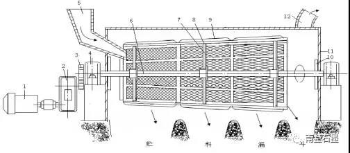
The cylinder screen is mainly composed of a transmission system, a main shaft, a sieve frame, a screen mesh, a sealed casing and a frame.
In order to obtain particles of several different size ranges at the same time, different sizes of screens can be installed in the whole length of the sieve. In the graphitization production, two different sizes of screens are generally installed, in order to minimize the particle size of the resistance material. And the materials larger than the maximum particle size of the resistance material can all be sieved out, the sieve of the small size sieve hole is placed near the feed inlet, and the screen of the large size sieve hole is placed near the discharge opening.
(2) Working principle of cylindrical sieve
The motor rotates the central axis of the screen through the deceleration device, and the material is lifted to a certain height in the cylinder due to the frictional force, and then rolls down under the force of gravity, so that the material is sieved while being inclined along the inclined screen surface. Gradually moving from the feeding end to the discharge end, the fine particles pass through the mesh opening into the sieve, and the coarse particles are collected at the end of the sieve cylinder.
In order to move the material in the cylinder in the axial direction, it must be installed obliquely, and the angle between the axis and the horizontal plane is generally 4°–9°. The rotation speed of the cylindrical sieve is usually selected within the following range.
(transfer / minute)
R barrel inner radius (meter).
The production capacity of the cylindrical sieve can be calculated as follows:
The production capacity of the Q-barrel sieve (ton/hour); the rotation speed of the n-barrel sieve (rev/min);
Ρ-material density (ton / cubic meter) μ – material loose coefficient, generally taking 0.4-0.6;
R-bar inner radius (m) h – material layer maximum thickness (m) α – the inclination angle (degrees) of the cylindrical sieve.
Figure 3-5 Schematic diagram of the cylinder screen
2, bucket elevator
(1) bucket elevator structure
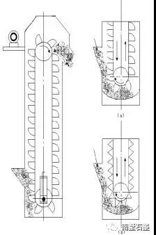
The bucket elevator is composed of a hopper, a transmission chain (belt), a transmission part, an upper part, an intermediate casing, and a lower part (tail). During the production, the bucket elevator should be uniformly fed, and the feed should not be excessive to prevent the lower section from being blocked by the material. When the hoist is working, all inspection doors must be closed. If there is a fault during the work, stop running immediately and eliminate the malfunction. The staff should always observe the movement of all parts of the hoist, check the connecting bolts everywhere and tighten them at any time. The lower section spiral tensioning device should be adjusted to ensure that the hopper chain (or belt) has normal working tension. The hoist must be started under no load and stopped after all the materials have been discharged.
(2) bucket elevator production capacity
Production capacity Q
Where i0-hopper volume (cubic meters); a-hopper pitch (m); v-hopper speed (m/h);
The φ-filling factor is generally taken as 0.7; γ-material specific gravity (ton/m3);
Κ – material unevenness coefficient, take 1.2 ~ 1.6.
Figure 3-6 Schematic diagram of the bucket elevator
Q-barrel screen production capacity (ton / hour); n-barrel screen speed (rev / min);
Ρ-material density (ton / cubic meter) μ – material loose coefficient, generally taking 0.4-0.6;
R-bar inner radius (m) h – material layer maximum thickness (m) α – the inclination angle (degrees) of the cylindrical sieve.
Figure 3-5 Schematic diagram of the cylinder screen
3, belt conveyor
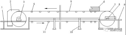
Belt conveyor types are divided into fixed and movable conveyors. A fixed belt conveyor means that the conveyor is in a fixed position and the material to be transferred is fixed. The sliding belt wheel is installed on the bottom of the mobile belt conveyor, and the belt conveyor can be moved through the rails on the ground to achieve the purpose of conveying materials in multiple locations. The conveyor should be added with lubricating oil in time, it should be started with no load, and it can be loaded and run after running without any deviation. It is found that after the belt is turned off, it is necessary to find out the cause of the deviation in time, and then adjust the material after the material is unloaded on the belt.
Figure 3-7 Schematic diagram of the belt conveyor
Inner string graphitization furnace
The surface feature of the inner string is that the electrodes are butted together in the axial direction and a certain pressure is applied to ensure good contact. The inner string does not need an electric resistance material, and the product itself constitutes a furnace core, so that the inner string has a small furnace resistance. In order to obtain a large furnace resistance, and in order to increase the output, the inner string furnace needs to be long enough. However, due to the limitations of the factory, and want to ensure the length of the internal furnace, so many U-shaped furnaces were built. The two slots of the U-shaped inner string furnace can be built into a body and connected by an external soft copper bus bar. It can also be built into one, with a hollow brick wall in the middle. The function of the middle hollow brick wall is to divide it into two furnace slots that are insulated from each other. If it is built into one, then in the production process, we must pay attention to the maintenance of the middle hollow brick wall and the inner connecting conductive electrode. Once the middle hollow brick wall is not well insulated, or the inner connecting conductive electrode is broken, it will cause a production accident, which will occur in serious cases. “Blowing furnace” phenomenon. The U-shaped grooves of the inner string are generally made of refractory bricks or heat-resistant concrete. The split U-shaped groove is also made of a plurality of carcasses made of iron plates and then joined by an insulating material. However, it has been proved that the carcass made of iron plate is easily deformed, so that the insulating material cannot connect the two carcass well, and the maintenance task is large.
Figure 3-8 Schematic diagram of the inner string furnace with hollow brick wall in the middle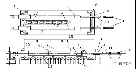
This article is only for studying and sharing, not for businiss usage. Contact us if delict.
Post time: Sep-09-2019